Search
Aerospace

eVTOL UAS with Lunar Lander Trajectory
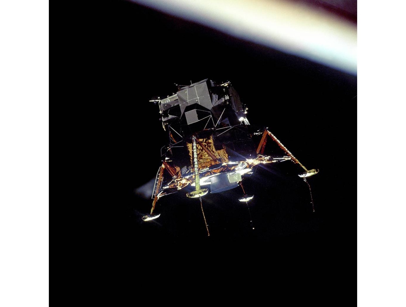
This NASA-developed eVTOL UAS is a purpose-built, electric, reusable aircraft with rotor/propeller thrust only, designed to fly trajectories with high similarity to those flown by lunar landers. The vehicle has the unique capability to transition into wing borne flight to simulate the cross-range, horizontal approaches of lunar landers. During transition to wing borne flight, the initial transition favors a traditional airplane configuration with the propellers in the front and smaller surfaces in the rear, allowing the vehicle to reach high speeds. However, after achieving wing borne flight, the vehicle can transition to wing borne flight in the opposite (canard) direction. During this mode of operation, the vehicle is controllable, and the propellers can be powered or unpowered.
This NASA invention also has the capability to decelerate rapidly during the descent phase (also to simulate lunar lander trajectories). Such rapid deceleration will be required to reduce vehicle velocity in order to turn propellers back on without stalling the blades or catching the propeller vortex. The UAS also has the option of using variable pitch blades which can contribute to the overall controllability of the aircraft and reduce the likelihood of stalling the blades during the deceleration phase.
In addition to testing EDL sensors and precision landing payloads, NASA’s innovative eVTOL UAS could be used in applications where fast, precise, and stealthy delivery of payloads to specific ground locations is required, including military applications. This concept of operations could entail deploying the UAS from a larger aircraft.
Manufacturing

Lunar Landing Pads
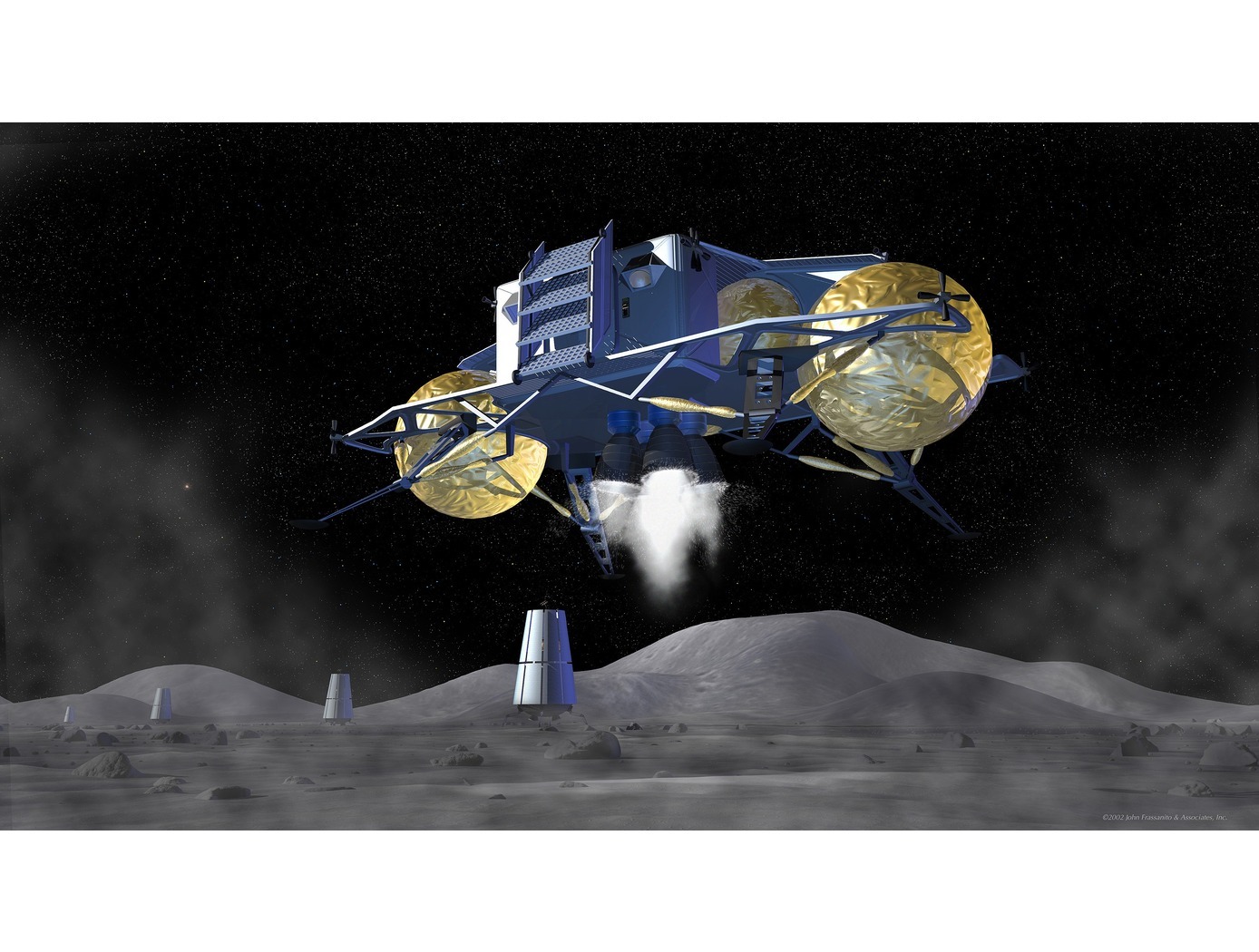
The jointly developed interlocking paver design consists of a molded solid material with tapered interlocking features that interface with features of an opposite gender in three orthogonal directions. This establishes a toleranced connection between the pavers that locks down six degrees of freedom.
More specifically, the system consists of two types of pavers: polygon and spacer pavers. Both are symmetrical about the longitudinal and transverse axes and are designed to interlock securely with one another in a checkerboard pattern. The polygon paver features an octagonal top level and a rectangular bottom level with protrusions and recessed notches. The spacer paver has an elongated center portion with isosceles trapezoid extensions on the top level and a rectangular bottom level with protrusions and notches. The interlocking design locks down six degrees of freedom, providing enhanced stability and preventing the flow of exhaust gases between the seams to mitigate erosion of the underlying regolith.
The pavers could be constructed leveraging in-situ resource utilization (ISRU). Lunar regolith has been identified as a potential construction material. Additionally, the pavers could be installed via robotic assembly, reducing the need for human labor in harsh environments.
Aerospace

Aerodynamic Framework for Parachute Deployment from Aerial Vehicle
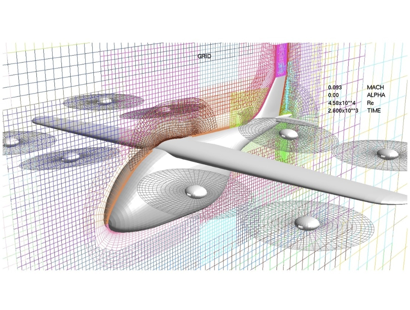
For rapid parachute deployment simulation, the framework and methodology provided by the simulation database uses parametrized aerodynamic data for a variety of environmental conditions, air taxi design parameters, and landing system designs. The database also includes a compilation of drag coefficients, thrust and lift forces, and further relevant aerodynamic parameters utilized in the simulated flight of a proposed air taxi. The database and framework can be constructed using simulated data that accounts for oscillatory breathing of parachutes. The methodology can further employ an overset grid of body-fitted meshes to accurately capture deployment of an internally-stored parachute, as well as descent of the air taxi and deployed parachute.
The systems and methods of the disclosed technology can be utilized with existing CFD solvers in a plug-and-play manner, such that the framework can be integrated to directly improve the performance of these solvers and the machines on which they are installed. The framework itself can employ parallelization to enable distributed solution of intensive CFD simulations to build a robust database of simulated data. Further, as up to 90% of computational time is spent in the calculation of aerodynamic parameters for use in coupled trajectory equations, the framework can significantly reduce the computational costs and design time for safe landing systems for air taxis. These reductions can lead to lower costs for design processes, while enabling rapid design and testing prior to physical prototyping.
Information Technology and Software

Rapid Aero Modeling for Computational Experiments
RAM-C interfaces with computational software to provide test logic and manage a unique process that implements three main bodies of theory: (a) aircraft system identification (SID), (b) design of experiment (DOE), and (c) CFD. SID defines any number of alternative estimation methods that can be used effectively under the RAM-C process (e.g., machine learning techniques, regression, neural nets, fuzzy modeling, etc.). DOE provides a statistically rigorous, sequential approach that defines the test points required for a given model complexity. Typical DOE test points are optimized to reduce either estimation error or prediction error. CFD provides a large range of fidelity for estimating aircraft aerodynamic responses. In initial implementations, NASA researchers “wrapped” RAM-C around OVERFLOW, a NASA-developed high-fidelity CFD flow solver. Alternative computational software requiring less time and computational resources could be also utilized.
RAM-C generates reduced-order aerodynamic models of aircraft. The software process begins with the user entering a desired level of fidelity and a test configuration defined in terms appropriate for the computational code in use. One can think of the computational code (e.g., high-fidelity CFD flow solver) as the “test facility” with which RAM-C communicates with to guide the modeling process. RAM-C logic determines where data needs to be collected, when the mathematical model structure needs to increase in order, and when the models satisfy the desired level of fidelity.
RAM-C is an efficient, statistically rigorous, automated testing process that only collects data required to identify models that achieve user-defined levels of fidelity – streamlining the modeling process and saving computational resources and time. At NASA, the same Rapid Aero Modeling (RAM) concept has also been applied to other “test facilities” (e.g., wind tunnel test facilities in lieu of CFD software).


